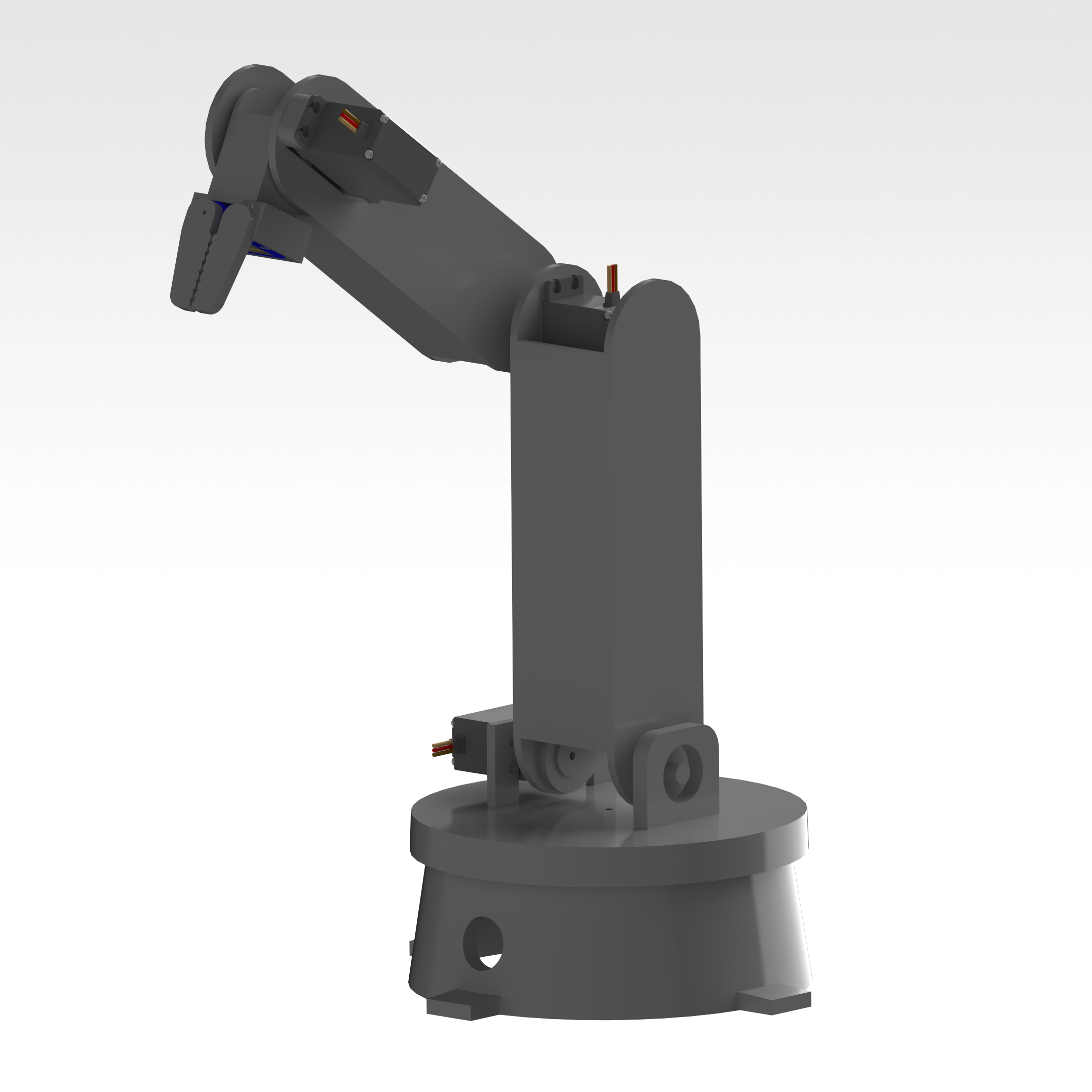
4 DoF Robot Arm
A 4-degree-of-freedom robotic arm designed and 3D printed in Siemens NX, focusing on kinematic analysis and workspace optimization.
The idea came to mind as a next step after the course Control of a flexible robot system. I enjoyed controlling the robot so much, that I decided I wanted to work on all parts of it myself. Since there was no opportunity for me to do that in the University, I made my own robotic arm.
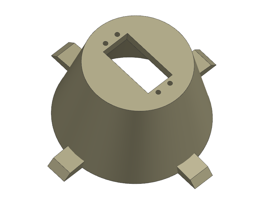
I started my design by researching how other people tackled this problem. After finding a couple of online resources, I was confident I could begin sketching a few prototype ideas. Moving through the design process, I eventually had a few parts ready for printing in Siemens NX.
Of course, there were multiple iterations and refinements along the way. This robot is still being continuusly improved, helping me learn how to transfer the theories I learned in my classes, into a real working robot.
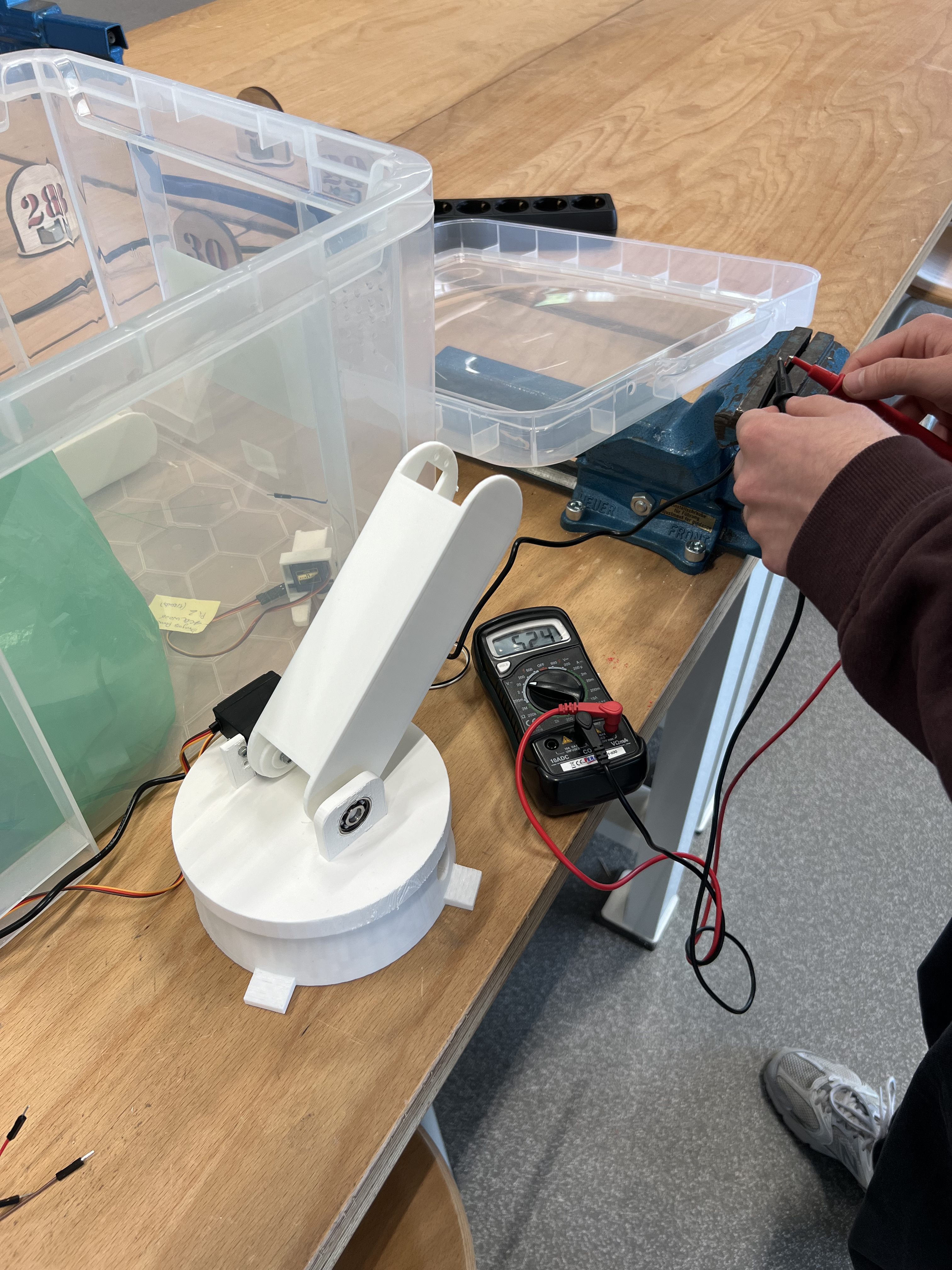
- To be determined, final assembly not finished.
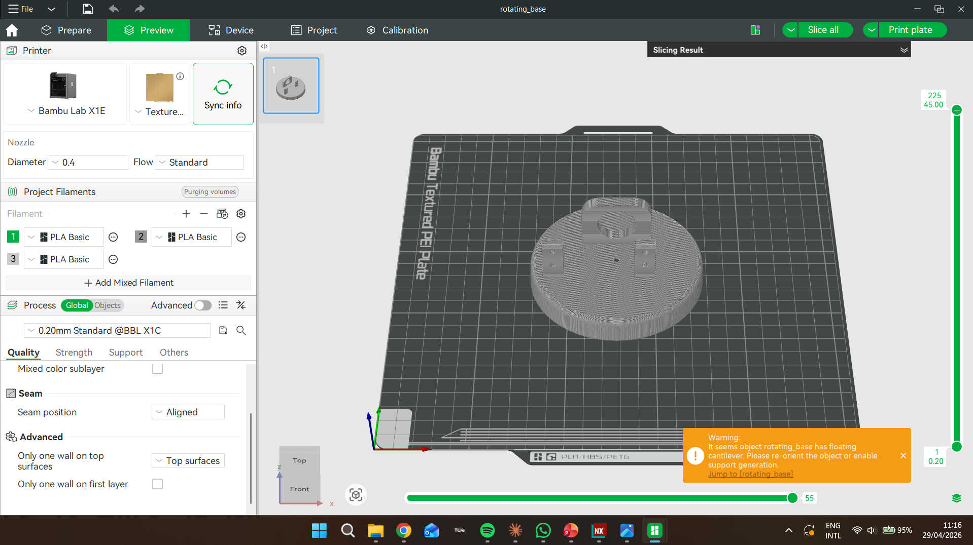
- Siemens NX (part modelling, assembly, Simulation)
- FDM 3D printing — PLA
- Arduino for coding
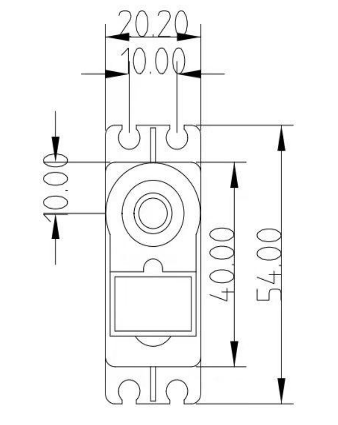
- Digital callipers for tolerance validation
- Multimeters and other electrical validation tools